

What Actually Determines Stone Road Construction Longevity
Stone road construction separates long-term performers from early failures at a single decision point — base design — and most project managers don’t catch the gap until they’re watching surface stone shift under load. The sequence of material choices below the finished surface matters more than any single product selection above it. Your aggregate gradation, compaction targets, and drainage geometry collectively determine whether your stone road holds up for 20 years or deteriorates within five.
Understanding the Installation Sequence
The complete installation sequence for stone road construction follows five distinct phases, each dependent on the previous one reaching a defined specification threshold before the next begins. Skipping a verification step doesn’t save time — it defers failure costs to a phase where correction is four to six times more expensive.
- Subgrade assessment and remediation before any structural aggregate is placed
- Sub-base layer with controlled gradation and verified compaction to at least 95% Proctor density
- Base course aggregate in two or more lifts, each compacted independently
- Setting bed or bedding sand layer graded to consistent depth
- Surface stone placed, bedded, and swept with joint-locking material
Your installation crew needs to treat these as hard gates, not checkboxes. Each phase requires a field measurement — not an eyeball judgment — before the next begins. According to Natural Stone Institute stone variety and application standards, improper base preparation is the leading cause of premature failure in natural stone road and driveway applications.
Subgrade Stability and Soil Conditions
The ground beneath your stone road isn’t just a platform — it’s an active variable that shifts with moisture, load cycles, and seasonal temperature change. Expansive clay soils present the most challenging subgrade condition in stone road construction. Clay that absorbs moisture and swells by even 2–3% of its volume will generate enough upward pressure to fracture a rigid stone surface within two or three wet seasons.
Sandy subgrades carry a different risk — not expansion but consolidation under load. Fine, loosely packed sand compresses unevenly under truck traffic, creating differential settlement that opens joints and tilts surface stones. The fix isn’t more aggregate on top; it’s geotextile fabric and additional compaction effort at the subgrade level itself before any structural material goes down. Caliche, common in arid regions, presents a hard but brittle subgrade that can fracture under point loads, creating voids that collapse into sinkholes beneath the road surface. You’ll need to break through any caliche pan layer and stabilize it rather than rely on it as a load-bearing platform.
- Clay soils: proof-roll the subgrade with a loaded truck and mark any areas with more than one inch of deflection for excavation and replacement
- Sandy soils: compact in thin lifts (no more than 4 inches uncompacted depth) and consider stabilization with Portland cement or lime at 3–5% by weight
- Rocky or caliche subgrades: break and compact fractured material, then verify bearing capacity before proceeding
- Organic or peat soils: full excavation to mineral subgrade is mandatory — no amount of aggregate depth compensates for a compressible organic layer
Conduct a simple field test before you commit to a design: the proof-roll test with a loaded dump truck moving slowly over the subgrade identifies soft zones that lab-tested soil samples sometimes miss. Any area with visible rutting or deflection exceeding an inch under that load requires remediation before you place aggregate.
Aggregate Base Specification
Your aggregate base is doing most of the structural work in a stone road. Surface stone distributes load horizontally, but the base layer is what converts point loads from vehicle tires into uniform pressure the subgrade can bear without failing. The gradation of your base aggregate matters as much as its depth.
Crushed angular aggregate — not rounded river gravel — is the correct choice for road base. Angular particles interlock under compaction and resist lateral displacement when loads are applied. Rounded particles roll under load, compressing unevenly and creating internal shear planes. You can source angular road base stone at Citadel Stone in the gradations typically specified for road construction, including AASHTO #57 and dense-graded base aggregate that compacts to a stable, interlocked matrix.
Base depth is not a fixed number — it’s a function of your subgrade bearing capacity and the design axle load. Light passenger vehicle traffic on a prepared clay subgrade typically requires 8–10 inches of compacted base aggregate. Heavy truck traffic or a weak subgrade pushes that to 14–18 inches. The USGS dimension stone production data confirms that natural stone road applications require significantly more engineered base depth than interior paving applications because the load dynamics are fundamentally different.
- Minimum base depth for passenger access roads: 8 inches compacted
- Minimum base depth for frequent truck traffic: 14 inches compacted, with sub-base below
- Maximum lift thickness before compaction: 6 inches uncompacted (reduces to approximately 4.5–5 inches compacted)
- Target compaction: 95% standard Proctor density, verified by nuclear densometer or sand cone test
- Gradation: dense-graded crushed aggregate, maximum 1.5-inch top size for road base
Drainage Geometry and Crown Design
Poor drainage is the silent destroyer of stone roads. Standing water softens the subgrade, migrates laterally under the base, and creates differential settlement that your surface stone simply cannot bridge. Your drainage design needs to address three separate water paths: water falling on the road surface, water moving through the base laterally, and groundwater rising from below.
Surface drainage relies on crown geometry — the slight transverse slope across the road centerline. For unpaved stone roads, a crown of 3–5% cross-slope moves surface water off the travel lane before it has time to infiltrate. The crown should be consistent along the entire road length; flat spots where crown reverses or disappears become ponding zones that concentrate erosion pressure.
- Crown slope: 3–5% transverse from centerline to edge, consistent along the full length
- Longitudinal drainage: the road should fall a minimum of 1% toward a defined outlet point
- Edge drainage: ditches or swales must be maintained to carry water at least 15 feet from the road edge
- Subsurface drainage: perforated pipe at the base layer perimeter where groundwater or seasonal saturation is a known condition
According to USGS dimension stone production and use data, drainage design failure is a consistent contributing factor in stone road and pavement rehabilitation projects across varied soil and climate conditions. Don’t treat drainage as an afterthought — design it into the cross-section before you place the first load of base aggregate.
Surface Stone Selection and Placement
The surface stone you choose for stone road construction needs to meet compressive strength, abrasion resistance, and freeze-thaw durability thresholds simultaneously. A stone that performs well indoors may fracture within two winters on a road surface exposed to de-icing salts and repeated impact loading.
Minimum compressive strength for road surface stone is generally specified at 10,000 PSI, with harder-use applications calling for 15,000 PSI or above. Granite, basalt, and hard limestone consistently meet this threshold. Softer limestone varieties and sandstone typically fall below it and should be reserved for foot-traffic applications. The Natural Stone Institute’s granite durability and application specifications confirm that igneous stones like granite deliver the abrasion resistance road surfaces require under repeated vehicular loading cycles.
Stone road construction using cobblestones or setts requires a setting bed of coarse bedding sand at 1–1.5 inches compacted depth between the base course and the surface stone. The setting bed accommodates minor irregularities in stone thickness and allows for minor adjustment during placement. It is not structural — the base course carries the structural load. Don’t use fine masonry sand here; coarse, angular bedding sand with particles in the 0.5–2mm range allows drainage while still providing uniform support across the stone’s bearing face.
Joint Filling and Surface Locking
The joints between surface stones are where stone roads most commonly begin to fail — not because joint material washes out, but because it was never compacted properly in the first place. Your joint-filling sequence needs to happen in two or three passes, not one.
For stone road construction using dry-laid cobblestone or granite setts, the joint-filling sequence works as follows: place joint sand or stone dust across the surface and sweep it into joints, then run a plate compactor over the surface to consolidate the joint material and reset any stones that shifted during placement. Repeat with additional joint material until joints are consistently filled to within 5mm of the surface. The final pass with a plate compactor locks stones in their final position and tests the installation under realistic vibration loading before it sees traffic.
- Joint material for trafficked stone roads: crushed stone dust or kiln-dried sand, never masonry sand
- Joint width specification: 8–12mm for cobblestone, 5–8mm for setts — narrower joints shed water better but allow less tolerance for stone size variation
- Compaction passes: minimum two passes with plate compactor after joint filling
- Post-installation settling: expect minor joint material loss in the first 30–60 days of traffic; plan one refill pass at 60 days
At Citadel Stone, we’ve found that one of the most common field mistakes is filling joints before the base course compaction has fully settled — usually a minimum of 24–48 hours after the final compaction pass in stable conditions. Premature joint filling traps air pockets that compress under early traffic loads, leaving visible joint voids within weeks of opening the road.
Project Planning and Material Quantities
Accurate quantity calculation prevents two costly problems: a material shortage that stalls your crew mid-installation, or a surplus that ties up budget and yard space. For a stone road project, you’re calculating quantities for four separate material categories: subgrade stabilization (if needed), base aggregate, bedding sand, and surface stone.
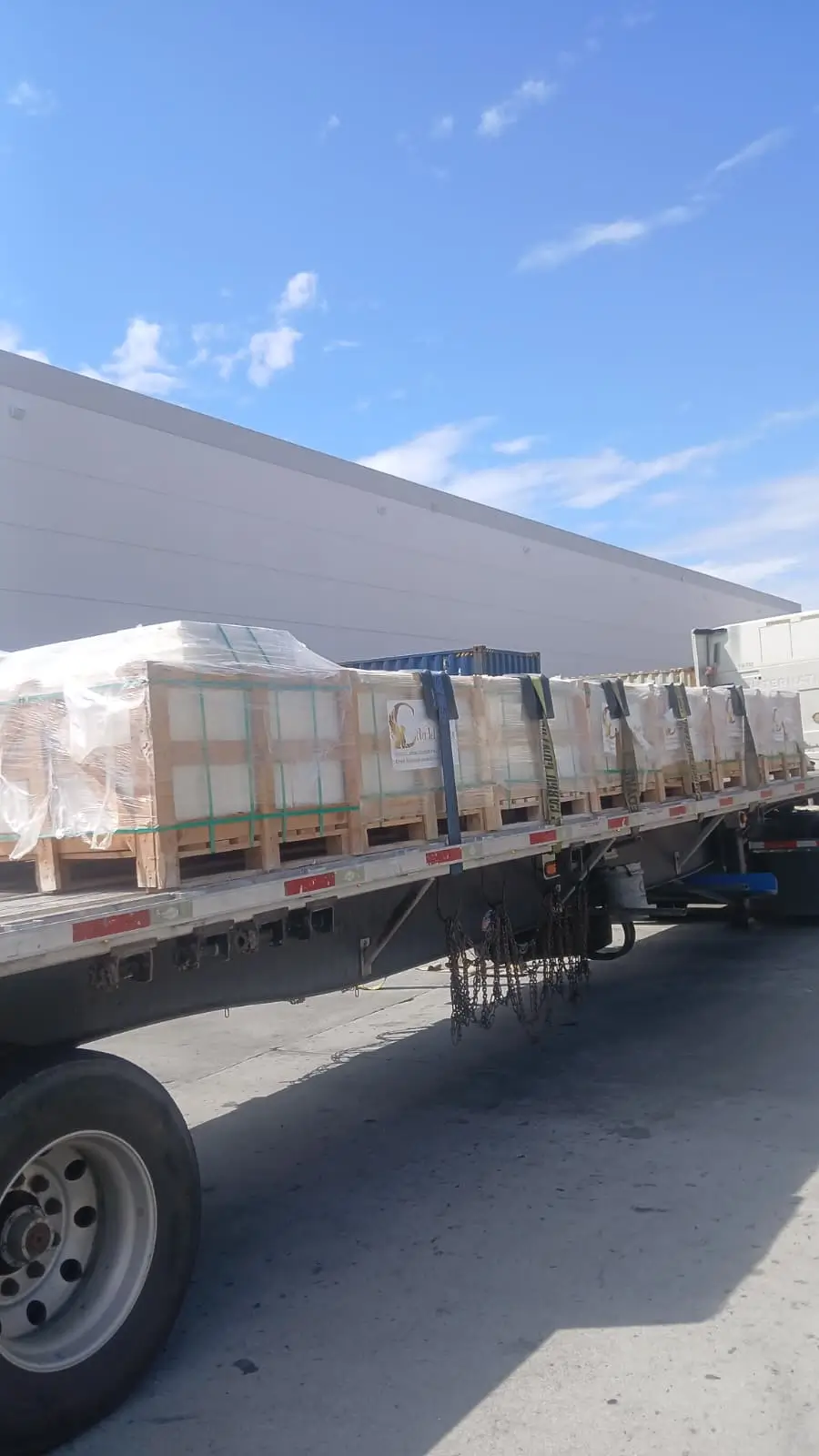
Your surface stone quantity calculation needs to account for a 10–15% overage factor to cover cuts, breakage, and pattern adjustments at edges and curves. Base aggregate quantities should account for 30–35% bulking factor — compacted depth requires significantly more loose material volume than the compacted volume suggests. Citadel Stone maintains truck-accessible warehouse inventory that allows staged deliveries timed to your installation phases, which matters for road projects where placing multiple full loads of base aggregate at once can create site management problems if your crew can’t keep pace with material placement.
- Surface stone: calculate exact coverage area, then add 12% for overage and edge cuts
- Base aggregate: multiply compacted depth (in feet) by area by 1.35 to convert to loose cubic yards
- Bedding sand: 1.5 inches compacted depth requires approximately 0.125 cubic feet per square foot of coverage
- Delivery scheduling: confirm truck access routes and turning radius before finalizing delivery timing with your supplier
Getting Your Stone Road Construction Specifications Right
Every stone road construction project comes down to execution precision at each phase gate. The material quality matters, but a premium surface stone placed over an under-compacted base on an unstable subgrade will still fail. Get the subgrade right before you place a single load of aggregate. Verify your compaction numbers with a densometer, not a visual estimate. Design your drainage before your crown, not after. Your stone road installation’s performance over the next two decades is almost entirely determined by decisions made below the finished surface before the first stone is set. As you think through related applications for natural stone in infrastructure and civil projects, how stone performs in railway track applications offers useful parallel insight into how aggregate characteristics under repeated dynamic loading translate across different civil uses. Road builders evaluating base materials find that Citadel Stone aggregate delivers the compaction and drainage performance that heavy traffic loads require over time.